Definition
A priority encoder is an combinational circuit that implements the priority
function.It is often used in scheduling interrupt requests.If two or more
interrupts arrive at the same time, the interrupt having the highest priority
will take precedence and get serviced first.
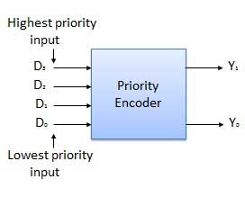
Block Diagram
General Equation
- A 4 x 2 priority encoder
has 4 inputs & 2 outputs (22 = 4).
- In general, an n x m
priority encoder has n inputs and m (2m = n )outputs.
Truth Table
Inputs
|
Outputs
|
|||||
D3
|
D2
|
D1
|
D0
|
Y1
|
Y0
|
V
|
0
|
0
|
0
|
0
|
x
|
x
|
0
|
0
|
0
|
0
|
1
|
0
|
0
|
1
|
0
|
0
|
1
|
x
|
0
|
1
|
1
|
0
|
1
|
x
|
x
|
1
|
0
|
1
|
1
|
x
|
x
|
x
|
1
|
1
|
1
|
Explanation
The
above Truth Table represents a 4 x 2 priority encoder.
Since
the priority encoder deals with priority signals assigned to input lines,
only one input is in ON (Binary - 1) state
at any point of time and the other inputs are in OFF (Binary - 0) state. So
only 5 (Five) combinations of inputs are possible(including invalid inputs) as shown in Truth Table.
Here,
D0 is assumed as Low Priority Input and D3 is assumed as
High Priority Input. There is Valid Output (V) that designates the validity of the servicing the input signal. If V=0, the inputs are invalid and if V=1, the inputs are valid.
When the truth values of all the inputs (D0
through D1) are '0', the outputs are not determined. So, we mark a 'x' (don't care) value.
When D0 = 1, the outputs Y0
& Y1 are '0' - means that it is a low priority input compared to D1,D2 &D3.
When D1 = 1, the output Y0=1 & Y1 =0 - means that its priority > D0 and less than D2 & D3.
When D2 = 1, the output Y0=0 & Y1 =1 - meaning
that its priority > D1,D0 and less than D3.
When D3 = 1, the outputs Y0=1 & Y1=1 - meaning that it is a high priority input compared to D0, D2 &D3.
When D3 = 1, the outputs Y0=1 & Y1=1 - meaning that it is a high priority input compared to D0, D2 &D3.
Design of Logic Circuit for 4 x 2 priority encoder
The Logic Circuit for 4X2 Priority encoder can be done using Karnaugh Map (K-Map).
Since there are two outputs (excluding V output), two 4 x 4
K-Maps are possible( one for the output Y0 & the second for the
output Y1).
K-Map for output Y1

K-Map Explanation for output Y1
Inputs for D3D2D1D0
|
Entry in K-Map for output Y1
|
Reason
|
0000
|
x
|
No output is generated when all inputs are 0
|
0001
|
0
|
Output 0 is generated for input D0 – No need to consider
the truth values of other inputs.
|
0011
|
0
|
Output 0 is generated for input D1 – No need to consider
the truth values of other inputs.
|
0010
|
0
|
Output 0 is generated for input D1 – No need to consider
the truth values of other inputs.
|
0100
|
1
|
Output 1 is generated for input D2 – No need to consider
the truth values of other inputs.
|
0101
|
1
|
Output 1 is generated for input D2 – No need to consider
the truth values of other inputs.
|
0111
|
1
|
Output 1 is generated for input D2 – No need to consider
the truth values of other inputs.
|
0110
|
1
|
Output 1 is generated for input D2 – No need to consider
the truth values of other inputs.
|
1100
|
1
|
Output 1 is generated for input D3 – No need to consider
the truth values of other inputs.
|
1101
|
1
|
Output 1 is generated for input D3 – No need to consider
the truth values of other inputs.
|
1111
|
1
|
Output 1 is generated for input D3 – No need to consider
the truth values of other inputs.
|
1110
|
1
|
Output 1 is generated for input D3 – No need to consider
the truth values of other inputs.
|
1000
|
1
|
Output 1 is generated for input D3 – No need to consider
the truth values of other inputs.
|
1001
|
1
|
Output 1 is generated for input D3 – No need to consider
the truth values of other inputs.
|
1011
|
1
|
Output 1 is generated for input D3 – No need to consider
the truth values of other inputs.
|
1010
|
1
|
Output 1 is generated for input D3 – No need to consider
the truth values of other inputs.
|
Expression for O1 derived from K-Map
For Minterms showing in (i) : O1 = D3

K-Map Explanation for output O0
For Minterms showing in (i) : O1 = D3
For Minterms
showing in (ii) : O1 = D2
Final Output
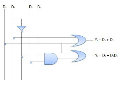
for O1 = D2 + D3 -------- (A)
K-Map for output O0

Inputs for D3D2D1D0
|
Entry in K-Map for output
|
Reason
|
0000
|
x
|
No output is generated when all inputs are 0
|
0001
|
0
|
Output 0 is generated for input D0 – No need to consider the truth values of other inputs.
|
0011
|
0
|
Output 0 is generated for input D1 – No need to consider the truth values of other inputs.
|
0010
|
1
|
Output 1 is generated for input D1 – No need to consider the truth values of other inputs.
|
0100
|
1
|
Output 1 is generated for input D2 – No need to consider the truth values of other inputs.
|
0101
|
0
|
Output 0 is generated for input D2 – No need to consider the truth values of other inputs.
|
0111
|
0
|
Output 0 is generated for input D2 – No need to consider the truth values of other inputs.
|
0110
|
0
|
Output 0 is generated for input D2 – No need to consider the truth values of other inputs.
|
1100
|
1
|
Output 1 is generated for input D2 – No need to consider the truth values of other inputs.
|
1101
|
1
|
Output 1 is generated for input D3 – No need to consider the truth values of other inputs.
|
1111
|
1
|
Output 1 is generated for input D3 – No need to consider the truth values of other inputs.
|
1110
|
1
|
Output 1 is generated for input D3 – No need to consider the truth values of other inputs.
|
1000
|
1
|
Output 1 is generated for input D3 – No need to consider the truth values of other inputs.
|
1001
|
1
|
Output 1 is generated for input D3 – No need to consider the truth values of other inputs.
|
1011
|
1
|
Output 1 is generated for input D3 – No need to consider the truth values of other inputs.
|
1010
|
1
|
Output 1 is generated for input D3 – No need to consider the truth values of other inputs.
|
Expression for O0 derived from K-Map
For Minterms showing in (ii) : O1 = D3
Circuit Diagram
Using (A) & (B) we can design the Priority Encoder circuit using AND gates and OR gates.
------- x --------
Using (A) & (B) we can design the Priority Encoder circuit using AND gates and OR gates.

------- x --------